Tuesday, August 17, 2010

Is Ham Radio Still Relevent ?

Is Ham Radio Still Relevant?


Bob Raynor N4JTE


I’m presenting this article to hopefully ask some pertinent questions that might inspire thoughtful discussion on where we’ve been, where we are now, and what does the future hold for Amateur radio.


Retrospective;

The origin and evolution of Ham radio clearly shows that we were blessed with some very talented innovators and experimenters.


In 1936 W9GFZ, Grote Reber was instrumental in the design and development of the first radio astronomy telescope; he built it out of wood and wires and started a whole new discipline in the science world. In 1935 Edwin Armstrong, among other radio inventions, laid the ground work for what we now call FM


 During the following 15 years the amateur community contributed many innovations we use today like SSB, the yagi antenna, 2 meter moonbounce and SSTV over amateur radio bands, before half the country had a TV in their living room.


It pays to remember that Hams launched their own communication satellite in 1961. Oscar 1 predated by 40 years the satellite worldwide communications we take for granted these days.


I, and many others probably set up their own HF and VHF repeater stations over 30 years ago, predating the cell tower culture by many years. We also introduced Packet and RTTY during that era while the internet was still in it’s infancy.

Sooooo, what have we done lately to match those advances?

Are we content with the advancement of Ham Radio on any level? Of course the radios are smaller and more powerful along with the good ol plug and play capability. If not for Ham radio piggybacking on computer technology we probably would have died from boredom by now. Are our wireless cell phone and internet emissions going out into space and competing with old Burns and Allen radio shows? Is it any wonder that some celestial visitor hasn’t graced us with their presence? To be fair, it could be 80 meters slowing down that first visit. Scientists tell us that computer memory is doubling every year and in 10 years a super computer will equal the process power of our brains pound for pound!

At this rate we will be living thru avatars and visiting Pam on the beach between our feedings in the nursing home.


It’s probably more fair to define the relevance of ham radio to our own experiences; possibly, but we as Ham operators live in our own box of blocks, sorta like preaching to the choir.

My favorite times on the radio revolved around being an NCS on the Maritime Mobile Service net running emergencies, phone patches for deployed military, Antarctic scientists and scared medical students in Granada. Well, that whole deal got antiquated in a heartbeat after Sat phones and GPS technology took charge. I got over it and adapted to other areas of interest in Ham radio but the fact remains that newer technology beat the pants off of that avocation.


What’s the Next Big Thing in ham radio ? Will it take an Armageddon to reacquaint the great tech savy crazed majority that a radio, a wire, and a battery will still allow communication between human beings ? Sorry no tweets !

Hell of a scenario but played out occasionally to indifferent ears during recent natural and unnatural disasters.


Is it fair to expect a Hobby to lead the way in technology ? Think about the RC airplanes we built and played with that evolved into the Predator taking out the bad guys.

Will there be an engineer or some Ham radio operator in our lifetime that will jump out of the box and design a super efficient HF antenna that doesn’t need towers and acreage? The laws of physics are being challenged/ changed every hour to explain the origin of the universe. So why not the good old, and I mean old, antenna theories we confine ourselves to.


Scientists are working on HFGW, high frequency ground wave propagation thru the Earth layers that has shown some remarkable progress and interesting results worldwide. Hope there a few Hams on that team.

I have to assume that most of us are content with where we are in the technology aspect of our hobby and take comfort in our ability to chat with friends, chase some DX or building antennas. Sure it’s a fun way to pass the time and keep in touch but I, for one, hope we can restore the incredible quest for progress and sense of urgency that the original innovators began, and somehow, take the baton finally and figure out some new ways to survive the challenge of competing in sterile and artificial technologies.


I am raising all these questions because it seems to me that Ham radio has stagnated and not kept up with its pioneering history of innovation and cutting edge technology. If you consider hooking up your radio to a computer as the paradigm of Ham radio then perhaps my age is showing.

What would be cool from my limited perspective would be an HF radio with a self contained power source that transmits 100 watts and weighs the same as a laptop. Or maybe a “caller ID” on received signals displaying the call sign, consider the ramifications of that little device. It would be enlightening to know what others would like to see on the Ham market in the near future.


I am sure that there are many ways for Ham radio to regain its promise and it’s

lead in cutting edge technology envisioned by those pioneers over 50 years ago.


What’s next? Are we just rearranging chairs on the Titanic??


Tnx for reading,

N4JTE


Tuesday, June 02, 2009


THE G5RV; What it is, What it ain’t!
A Real World Comparison.
Bob Raynor N4JTE


During the last 5 or 6 years I have built 38 homebrew antennas, both wire and verticals from 160 thru 2 meters. Most of these were monoband gain arrays. I have never tried a G5RV so a few weeks ago I set out on this experiment.
The G5RV has been well represented on the bands and well disparaged in other venues of opinion. I figured why not build one and compare it to some other antennas in equivalent directions and find out for myself !
This article is aimed at a new ham considering a multiband coax fed wire antenna that is easy to build and costs less than a commercial single dipole. I would hope that my observations will be of use to a beginner and perhaps also to some of my crusty contemporaries.
As designed by Varney, the G5RV, is in essence, a slightly long, extended double zepp on 20 meters with an ½ wl tuned stub. The basic EDZ will ordinarily be fed with an 1/8 wl tuned stub in the monoband configuration.
The classic G5RV is a center fed 102ft. long wire fed either with 300 twin or 450 ohm ladderline, 31 ft. or so long, depending on the choice. It is non resonant within the ham bands but is actually close enough to tune out the resultant swr and work well with the internal tuners prevalent in the newer transceivers.
CAVEAT: Stick with the original design and lengths and flat top if possible. This antenna has a bunch of well thought out compromises and Varney knew what he was doing. I attempted to optimize 20 meters by trying 10 different tap points on the 450 line and found that the 31ft. was the best, but I had to try, hi. Also, http://www.w8ji.com/ , Tom has a good swr scan at 100 ft. high ,mine at 38 ft was pretty close so check his out if interested.

COMPARISON ANTENNAS;

1; My G5RV was built in the classic design and was flat top at 38ft. with a center support and two available trees. Due to their location the actual horizontal angle was about 165 degrees as opposed to the preferred 180.
Antenna was fed thru 100ft. of RG 213 to a MFJ-986 differential tuner.

2; 40 meter double extended zepp, 165ft long at 60 ft high. Ladderline fed direct to ATR-30 tuner. Both antennas favor the E/W direction and were about 80ft. apart.

3; 2 pairs of 40 meter phased verticals covering NE/SW/SE/NW, switchable.

4; 20 meter diamond shaped quad loop at 40 ft. in E/W favor.

5; 17 meter monoband vertical at 35ft. high with 4 sloping ground plane radials at 22ft high, 45 degree slope.

ON AIR TESTS:
The testing was done during May of this year (2009), over a 4 week period with the usual zero sunspot activity with an occasional short duration small cycle 24 sunspot showing up. All tests were A-B-C, instantaneous and no antennas were identified until later discussions at the end of the qso’s.

75 METERS.
Antennas; G5RV and 40 meter zepp/doublet.
1900 utc to 0500 utc
Stations contacted; 124 Stateside
12 DX
The overall consensus was that 95% of the stations worked could not discern any significant difference between the 165ft. long zepp and the G5RV. What was truly astounding was that I tried the same test on a few of the same contacts and told them which antenna I was now on. Amazingly, somehow the G5RV was now getting a 1 S unit lower report than before being named.
Go figure, hi.
The G5RV is only about 20 ft. short as a dipole on 75 so I was not totally surprised that it held up well against, in this case, a 165 ft. long doublet. I had expected a little more advantage for the doublet being longer and higher but the result speaks for itself. I did run into some RF into the laptop on the first night of testing but a 1 to 1 balun at the ladderline /coax connection took care of the problem and remained connected for all testing.

40 METERS;
Antennas; G5RV
40 meter 4 square
40 meter EDZ
1500 utc to 0500 utc
Stations contacted; 186 Stateside
22 DX
I really put the G5RV to the test on this band as I have multiple gain/direction antennas well proven on this band for stateside and dx contacts.
During local daylight the G5RV held it’s own, and them some, with many stateside contacts and rag chews. When working multiple states at the same time the G5RV was the antenna of choice with all stations receiving and being heard well. The G5RV filled in the missing South and North lobes on the zepp and made for a more comfortable roundtable between MI, SC, VA, ME and NY. Both gain antennas showed a couple of S units gain when pointed at their locations but the G5RV saved a lot of time switching around and served very well in this capacity.
So; during daylight the G5RV on 40 meters was a delight to this beam/array operator as it had no problem being heard as well when put up against 3 dbd gain directional arrays. I could not see, nor document, any particular lulls on receive or transmit that would indicate any pronounced directionality with the G5RV. The G5RV has become my 40 meter daylight antenna of choice.
Nighttime testing on all paths was very enlightening in that again the G5RV was competing against two antennas designed for distance and gain.
The best example exhibited was during a test between HI and a G4 along with 56 stateside checkins on my http://www.omiss.net/ one night.
To Hawaii, the G5RV was given 5/7, the Zepp was given was given a 5/9 and the phased verticals were given 5/9 plus,(better aimed, hi). To the G4 the G5RV was 5/7, the zepp was 5/9 plus a roomful and the phased verticals had a similar report. There were many other dx contacts made during the testing period but I notated this one for the fact that both HI and England were available for testing at the exact same time. Is the G5RV a pile up breaker on DX, No. Will it be heard and worked on 40 meters when the beams/ arrays are done calling and are chasing someone else, Yes !
I was very happy with the G5RV on 40 meters as it compared well with some tough competition over 4 weeks, day and night. Bottom line is that I was impressed enough to take down the 4 square on 40 for the summer and rely on the zepp and the G5RV on this band. To be honest, I also need to put in an above ground pool. But if the G5RV did not work as well as it does the pool idea would be history.

20 METERS;
Antennas; G5RV
40 meter zepp/ doublet
Quad loop at 40ft.
1700 utc to 2200 utc.
Stations contacted; 53 Stateside, 9 Dx.

All contacts were made from here in N.Y. during midday. A test I really wanted to try was a simple dipole at the same height vs the G5RV, but I could not find a way to build them in the same direction without encountering mutual coupling, I tried, but no way! So I put up a diamond shaped single quad loop at 40 ft. coax fed, with a resultant 1.7 to 1 swr favoring E/W for extra comparisons.
The band propagation on 20 meters was pretty crappy during the 3 week period I had the time to test things but at least the playing field was level for all 3 antennas.
The only pronounced plus difference (3 S units), was shown by the G5RV when working Mexico and the Azores as compared to the doublet and the loop.
All the stateside contacts reported non discernable differences between the doublet and the G5RV, the quad loop was always a distant 3rd in all comparisons. Not having a clue what the lobes really look like on the 40 EDZ, I’m guessing that the G5RV has a small gain in it’s favored directions over the zepp and the quad loop.
The G5RV proved itself as a basic, competitive wire antenna on 20 meters with perhaps some gain over a dipole and full sized vertical loop in the same direction.

17 METERS;
Antennas; G5RV
17 meter monoband Ground plane vertical at 33ft.
Daytime
Contacts; 11 Stateside, 2 DX

Another band with hit and miss propagation, but enough to give some real world results. It has been said by some that the G5RV will not work on 17 meters, well, I will leave others to define “work”. The swr on the G5RV was around 9 to 1, but it loaded up easily on 18.165 on the MFJ versatuner. The 40 meter zepp/doublet will not load up on this band so I built a 17 meter monoband vertical at 35ft tall with 4 raised radials sloping off at 45 degrees around 22ft. off the ground. SWR was 1.2 to 1 and direct coax fed.
As I said, the propagation was hit and miss but when the band was open both antennas worked exactly the same with a 5/9 here and a 2/2 there, across the country, Cuba, and the occasional South American contact.
Whether both antennas stink the same or work, will only be up for conjecture till we get some real sunspots. At least the G5RV will at least let you know when the band is open so you can aim your 6 element monobander in the right direction.

FINAL COMMENTS;

I did not try any tests on 15 or 10 meters because the band is abysmal up here in NY when I can get near it, but for information purposes, the G5RV loaded up easily on both bands and on 10 meter FM, it actually opened some repeaters in NY and MA.
OVERALL, I feel that the G5RV, after 220 plus contacts, is an excellent trapless, multiband coax fed antenna well suited for a beginner to build. As detailed during the article, it compared extremely well with a ladderline doublet and various other configurations in real time comparisons.
I hope some of the observations and comments provided here will give the antenna experimenters out there some real world, non biased, on the air comparisons to think about while perhaps practicing on their modeling programs.

Thank you Mr. Varney; G5RV, you left us a good one!

Tnx for reading.
Bob N4JTE

Wednesday, April 15, 2009

N4JTE 6 BAND 'RIBBON" ANTENNA $35


N4JTE; 6 BAND “ RIBBON” $35 ANTENNA
------------------------------------------------------------------------------------------
This antenna article is geared towards new Hams and antenna builders
looking for a very inexpensive 6 band antenna that can be efficiently fed
with 50 ohm coax without a tuner.
The inspiration for this design resulted from a visit to my 82 year old
neighbor’s home who had asked me for some help in dismantling his
amazing and increditably beautiful model train set, and box up for his
grandson. During this process I was intrigued by his use of 5 and 10
conductor 18 gauge flat insulated ribbon cable for all of the L.V. switching
and action devices.
So Begins the Adventure.


To be honest I am getting more and more frustrated with some of the latest
marketing ploys being used by commercial antenna manufacturers and their
incredible, misleading and unsubstantiated miracle “all band” antennas that
will sucker in some poor unsuspecting new ham who will spend his money
on a heavily marketed, overpriced, and in some cases, Amazingly reviewed
antenna // Toaster.
Mt plan was to use this relatively cheap insulated wire and find out if was
actually possible to get 6 bands cleanly matched to 50 ohm coax. As this
antenna was basically built for testing and performance evaluation the
construction details are limited and somewhat primitive by most standards
so I will leave it to others to refine and permatize, hi.
When I envisioned this concept my only real concern was how all the close
spaced wires would inter react. The shorter dipoles will all present high
impedance at the feed point when they are not driven forcing the feed line to
pick the path of least resistance and best match for the frequency. The 40
meter wire will serve well on the 15 meter band as a center fed 1.5 wl wire.
I am aware that a fan dipole uses the same single feed concept but I believe
the Ribbon antenna eliminates all those extra tie off points while maintaining
the resultant extra effective radiated height, especially if used in a flat top
configuration. Certainly less obtrusive and much less work.
BUILDING IT:
Well you have to start somewhere, so I chose the OMISS net frequencies
available at www.omiss.net, as my starting point for the band frequencies
and wire lengths. I have built more than enough monoband Inv. Vees at this
location with insulated wire so I use my own formula of 450/ freq. to
achieve what I’m after with minimal pruning.
You need to approach this antenna one side at a time. The ribbon wire I
purchased was only available in 50 ft. lengths so I knew the 75 meter wire
would need about 8 more feet to each end to reach 75 meters. It’s best to
unroll and stretch the wire out to remove the “wire memory”. That
accomplished measure out your 5 chosen ¼ wl lengths and mark or tape off.
As the 75 wire is pretty much done after adding the required wire, separate
the next wire, and carefully peal back to the taped off marker and cut off
excess. Continue this process for the remaining wires up to the 10 meter
point. Yeah I know it seems like a lot of wasted wire but at 6 cents a foot
you’ll get over it !
Repeat the process with the other half of your antenna. I just laid them along
side each other and matched all the lengths. Be careful to use a dull knife or
fingernail file to separate the wires so as to not break the insulation.
After cutting all your wires to length you will need to have some kind of
center support and feedline connector in mind before stripping and soldering
the 5 conductors together. In my case I pushed each one thru a ceramic
insulator and then carefully stripped and soldered together in preparation for
feedline attachment.
The ends of half wave dipoles are at high rf voltage and if too close to others
will add unwanted capacitance and tuning problems. For starters I just
separated the adjacent wires by about a foot and let them dangle down.
FIRST ATTEMPT.
My goal with this initial attempt was to see basically where or if ,I would get
full power out. This would give me the best indication of what was actually
radiating and at what frequency. You cannot expect, nor limit yourself, to a
1 to 1 swr as being your goal. The meter will serve only as a guideline to
where your wire length and height works in the real world of your backyard.
A quick look at any antenna book will show the relationship between height
above ground and radiation resistance in ohms. This inv. Vee at 43 ft. is
even a little more tricky to predict especially when the 75 meter antenna is
only at .175 wl high and the 10 meter antenna is at 1.2 wl above real ground.
All 6 antennas should range between 20 and 90 ohms with the ends at 10 ft.
above ground. The results of the first attempt were very interesting in that at
least I was getting full power out somewhere close to the 6 bands of interest.
I had my doubts because of introducing the 17 meter antenna into the mix
which is not an even multiple of the lowest band, usually considered a no no
on multiband antennas
.
--------------------------------------------------------------------------------------------
SECOND ATTEMPT:
I use an eye hook stuck into the top of the fiberglass pole with a masonry
string to allow easy up and down access for the cutting and tuning process. I
started by adding about 4 ft to each end of the 75 wire and after some
diddling ended up with around 3.95m. the only band affected by this change
when scanning thru the bands was the 40 meter wire which changed it’s
apparent resonant frequency to 6.9M and the 15 meter wire also dropped in
frequency. A quick trip to the backyard to shorten each end of 40 wire by
one foot made no change on the resonance. I then separated the forty from
the 75 by dangling about 3 ft. at each end. Obviously the end effect was
kicking in because I ended up at 7.1m, close enough for my needs and the
15 meter wire was happy in the middle of the SSB portion.
FIRST TRY RESULTS
75----------4.179m short
40----------7.290m short
20----------14.190m okay
17----------17.800m long
15----------21.553m long
10----------27.713m long
SECOND TRY.
75--------------3.95m
40--------------7.1m
20--------------14.190m
17--------------17.800m
15.--------------21.300m
10--------------27.717m
THIRD ATTEMPT:
The only bands left to fine tune were the 17 and 10 meter wires which were
still too long, so I cut off 6 ins. From both ends of each antenna. The 17
meter ended up at 18.135 and the 10 meter at 29.5 in the FM portion of the
band which I actually prefer these days.
.
RECAP:
The whole tune/recut exercise took about 6 hours and resulted in a 6 band
antenna that will radiate full power out without a tuner. Due to the fact that
there are no traps, no loading coils, no tuners and no ladderline needing a
balun to match, the only losses will be in the feedline due to it’s length and
not the result of any mismatch at the antenna feedpoint. I do not have the
necessary brain power to model this design and would appreciate a peer
review on the modeled radiation resistance and resultant antenna patterns.
Point of interest; The 60,30 and 12 meter bands had around a 3 to 1 swr and
were showing 60 to 70 watts out without a tuner. Probably work well with
auto tuner.
IF YOU BUILD IT:
1; A simple Plexiglas T, or equivalent with double slots for the ribbon wire
and two small holes to tie wrap the coax should be more than enough after
waterproofing to ensure stability and strength for a center supported light
weight antenna such as this.
2; The 75 wire ends up holding the whole antenna up, so I would attach
some masonry string to the center insulator and tie wrap at the band end
dangles and a couple of more at the 40 and 80 wires with the string going to
tie off points. By tie wrapping you will also prevent the wires from
separating at band junctions.
3; Attach small non conductive weights at the drop wires after final tuning.
THIRD, FINAL TRY, I’m lazy:
75----------------3.95m
40.---------------7.1m
20----------------14.190m
17----------------18.135m
15----------------21.360m
10----------------29.500m
4; Use a tuner at higher powers to attenuate harmonics and any possible
spurious transmitter outputs.
5; If 10 conductor wire is available you can double up the wires for each
band providing an increase in bandwidth and power handling. FYI, I had no
problems with the 5 wire at 500 watts ssb.
FINAL COMMENTS:
I am not going to waste everyone’s time by recounting all my log entries
while testing this antenna. I will tell you it is a joy to run from 75 to 10
meter fm and be able to hear what is going on and respond to a cq without
fumbling around with antenna switches and tuners. This antenna is nothing
more than 6 inv vees at 43 ft. that perform to the laws of physics and will
serve you well if you are committed to a little sweat equity to get it working
efficiently.
You will not be disappointed with this $35 antenna.
BUILD ; DON’T BUY !
Tnx for reading,
Bob N4JTE

Wednesday, February 04, 2009


80 Meter Vertical Experiment;
Bob Raynor N4JTE

I have spent most of my creative antenna energy on 40 meter wires and have had great success with those experiments. HOWEVER, the 40 meter band shuts off like a light switch here in upstate NY a couple of hours after sunset.
Having had a lot of unexpected fun with phased verticals on 40, I researched a way to get the same benefits on 80, as it seems to be the only band available after dark.
Problem is I don’t have two 60ft towers laying around, I know spiderbeam sells them for about $250 but not wanting to spend that much on an “experiment” I was forced into finding a way to use my existing 40ft poles.
I only ventured into phased verticals after figuring out an accurate way to cut feed and phaselines as detailed in previous articles. That epiphany opened a whole new area of experiments for the lower bands. The other revelation that got me going was the value of the Christman method of obtaining correct phase angles using 50ohm coax in place of complicated L/C constants which are beyond my math/circuit board experience.


THE PLAN;
Ø Utilize 2 available 40ft. pushup poles spaced 1/8 WL apart and achieve the theoretical gain of 3DBD in switched directions.
Ø Incorporate the phaselines as detailed by ON4UN in his bible, “Lowband DX’ing.” Based on the unique qualities of 135 degree phasing.
Ø Top load the 33ft. existing verticals with a (T) loading wire of appropriate length of #18 insulated wire to achieve resonance.
Ø Cut (2) phase lines at 157 degrees and (1) delay line at 39 degrees,
Ø Wire up 12v DPDT relay to achieve reverse capability.
Ø Wait for snow/ice temperature to go above 18 degrees!

THE REALITY;
My understanding of shortened verticals tells me that any loading system should be as close to the top as possible, I queried my fellow Elmers on Eham and and realized pretty early on that a coil at the base would be far from ideal. Adding wire at the top is the way to go and my lazy alternative of adding bottom fed coils was rejected.
If ON4UN is correct, and he usually is, he tells us that if the vertical is not less than 66% of 1/4WL height, you will have close to the same gain and front to back as that of a full size antenna array. You will be handed a narrow bandwidth, but that can be a matter of choice when designing the antenna and the use of a matching network at the antennas will expand your range of operation.

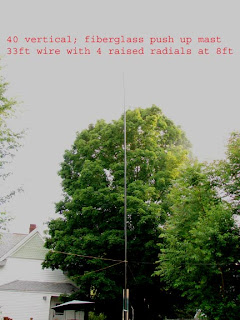
The first step was to top load one of the existing 40 meter verticals and achieve resonance at 3.7 megs. I cut a piece of 18 gauge insulated wire to 30 ft. and exposed the center and attached it to the vertical 33ft. wire. Before raising it back up I attached some masonry string to the ends to facilitate tying off in opposite sloping directions.

With 2 raised radials, resonance was above my target frequency so I lengthened each end of the top loading wire until I got close enough. I checked resonance, lowest swr, at the radio instead of antenna base because I don’t trust the MFJ at low frequencies due the fact we have a local am/fm station less than 1 mile away that could possibly skew the readings. A lot more trudging in the snow but worth the effort as this way the whole “system” is being measured.
The sequence was repeated on the second vertical while taking pains to keep the top loading wires parallel to the other vertical’s. Not sure why, but my instincts tell me that the mutual coupling of 33ft. should be maintained on the vertical and T wires.
I rechecked the resonance of the first vertical and noticed a slight increase in the resonant frequency. I could probably have spent a few more hours freezing my butt off to fine tune it, but I’ll save that chore for spring!

Reversibility;
I have existing poles in an East/West orientation as it seems the best compromise for DX and stateside contacts from my home here in upstate NY. I believe the verticals are fairly broad, somewhere around 135 degrees so that’s where they going to stay for this experiment.
The relay was wired up with short alligator leads as detailed in previous articles again taking care to maintain polarity. The phase line of 39 degrees was cut out of 50 ohm coax and ended up around 15ft. The 157 degree feedlines ended up around 63ft.each.
I never rely on published VF except to get a general idea of approximate length then I use the MFJ to get the exact readings, also spelled out in previous articles.
Not shown for clarity is the feedline to the shack nor the 12volt wire from power supply in shack, 3amp Radioshack.

Performance;
Remember when I said I would wait till Spring before getting both verticals exactly frequency matched? Well, preliminary testing as built was not outstanding. One antenna showed a 1.2 to one swr and the other was 1.8 to one, impossible to switch directions effectively. So before continuing on air testing, I put on the Carharts and ventured back out into the 13 degree weather to make both antennas resonant on 3.700 by adjusting the top loading wire lengths, not fun in these temperatures! That mission accomplished, I thawed out and was rewarded with a 1.2 on each wire in both directions, no tuner needed for a change.
My comparison antenna is a 40 meter EDZ at 60 ft and very close to resonance at 3.700
Did the verticals work ? Absolutely, I got significantly better reports, 3 to5 S units from various European stations as compared to the dipole and I had the same results with CA. contacts. This antenna works well but is very narrow banded. I did not lose too much in the 400 to 1000 mile range probably due to the sloping top wires. The horizontal component was not completely cancelled out as would be the case with flat top loading.


Final Thoughts;
This antenna will maximize your signal on 80 in a relatively small footprint with a very small investment as compared to store bought shortened miracle antennas. I probably will invest in a couple of 60ft. poles and eliminate the time consuming top loading and resultant narrow bandwidth. But for now I will be happy with doubling my ERP in opposite directions. And while the snow keeps burying all the mess I made in the backyard, I will be reading ON4UN’s book by the fireplace for the 5th time, looking for the next big idea. Maybe phased inverted L’s for 160 meters! Stay tuned.

Tnx for reading,
N4JTE
Poor Man’s 40 Meter 4 Square;
Submitted by N4JTE.

A few months ago I submitted an article titled; “Verticals; Got 2 ?”, which basically presented a simple, yet effective, way to phase a couple of vertical wires and make them reversible while achieving a relative gain of 3dbd and a surprising degree of front to back capability based on ON4UN’s design/ modeling specifications.
It worked very well considering I miscut the phase/ feedlines due to my screwed up formula at the time.
As luck/ misfortune, would have it, I had to head back to Fl. for a construction contract and could not continue that experiment.
Now that I am back in upstate N.Y. I decided to rebuild the two ele phased verticals with the corrected feedline and phase lines lengths, in the snow and freezing rain of course. It worked extremely well with significant front to back etc. so I decided to try another phased pair in the opposite directions and hopefully achieve a “ Poor man’s 40 meter 4 Square”

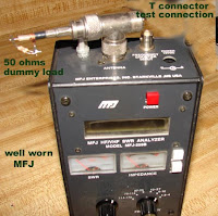
First; a quick recap from the previous article which detailed how to accurately cut feedline lengths by using the MFJ with a parallel 50 ohm load based on the fact that a true 90 W/L degree line will exhibit the lowest swr with the end shorted of a 50 ohm coax. At lowest swr/ reactance the frequency displays the 90 degree frequency under test, Simply shorten coax carefully in small increments until you are at the degree/ frequency you need.

Formula for feedline length based on freq. readout on MFJ.
84/90= 7.185/X = 7.698
71/90= 7.185/X = 9.107. Very handy way to cut the four 84 degree feedlines and the two 71 degree delay lines required to feed each pair of verticals correctly and achieve the gain and reversibility as detailed by ON4UN.
My antennas are designed for 7.185 so my feedlines had to be resonant at 7.698/ 21 ft. and the delay line needed to be at 9.107/ 15 ft for the RG58 coax. Far enough off of the published VF to make this technique the way to go if you want it accurate.

I am fully aware that what I am going to describe here is not a true 4 square in the classical format and this experiment does not take advantage of the inherent parasitical interplay of 4 verticals at the corners of thirty three foot sides on the square. However I do not have an extra $400 for the hybrid phase system nor the required real estate for the classical design.

DETAILS;
Rather than make this a” how to build” article, I will give the basics and welcome any further questions via email.

1; The NE/SW antenna is (2) 33 ft. long insulated # 12 wires vertically supported by 2 fiberglass push up masts at 40 ft. This ends up with the raised radials about 6 ft. high. I used 2 radials on each antenna for experimental/ laziness purposes. The distance between poles is 33ft. ¼ W/l.

2; The E/W antenna pair was strung from a catenary string between the available maple tree and an old rohn push up with the top part using about 16 ft of fiberglass to hopefully avoid any interaction with the two 33ft wires hanging down. Also at 40 ft high to allow for the two raised radials.

Both pairs of verticals are 33 ft. apart and fed with identical feed systems utilizing 84 degree feedlines from the relays and a 71 degree phase line inserted between the feedlines. This setup will obviously need two separate feedlines to the relays. You can however run the same 12v supply in parallel without affecting the patterns, I think !
Make all antenna wire lengths the same and while I have had excellent success with 2 radials of equal length, others might want to add more if space allows and adjust for better apparent matching. Do try to keep radials from being parallel to each other as they will skew pattern and loading.

Feed System;


I soldered short alligator clips to all the stubs for ease of connection in the field. The addition of 71 degree delay line adds the reverse ability to the two elements and the force feeding as per Mr. Christman makes for an easy method for equalizing voltage and impedance at each element. The addition of 12 volts to the relay instantly reverses direction, nice !

Operation;
To achieve the 4 direction capability I fed each pair of verticals at the relay with RG13 which was brought into the shack and connected to the coax 1 direct and coax 2 direct of my MFJ tuner
I ended up with about a 1 to 8 swr on both pair of antennas, not bad and not unexpected as my radial layout is pretty lame and temporary for testing purposes. With relays off I dedicated one array to the Southwest and the other array due East. With a little practice it became second nature to flick on the power and change directions. I put the feedlines thru the tuner and got down to 1.2 to one for both antennas with additional tuning, kinda split the difference. I am running an AL80B thru this setup so it was important to match up a little better.
Also; the relays have no problem at 600 watts..

On Air Results;

Well I must admit that my testing on 40 has been limited to mostly daytime due to non existent nighttime prop here in upstate N.Y. past 6pm since returning 2 weeks ago from Fl. but on air testing around the Country and Canada was very rewarding. The 4 to 7, S units front to back and reported signal strength differences in 4 directions is well worth the effort. I expect when 40 comes out of its nighttime coma here I will see more dramatic results.
I still have a 40 EDZ at 65 ft. which was used for a reference in similar directions with the appropriate phased verticals and they certainly held their own and then some. My EDZ is now my 75 antenna, don’t need it on 40.

Final Comments;

As mentioned, I did not overly detail the whole construction process here as I would hope that others will explore the concepts presented on phased verticals and improve and adapt the design to their own needs.
If anyone needs more details; email me at bobr1919@hotmail.com.

Regards to all.
Bob N4JTE

Thursday, July 10, 2008

Wire Antennas: The Good, Bad, and The Ugly:

Tuesday, July 08, 2008


N4JTE; On the Road Again
Where there is a will; there is a way!

Thoughts on getting an antenna up and working in challenging situations.


I am in the construction industry and with the economy in major upheaval I had to leave behind a very nice antenna farm in my backyard in upstate NY and get on the road to pay the bills.

Yep, there is an antenna or two in there, trust me!

First stop was Ft. Lauderdale, Florida for a couple of months R&R and a lame attempt at a job search while enjoying the view and the ocean. I missed ham radio and decided to attempt to lasso a nice 70 foot palm tree next to my triplex on the beach and enjoy the best of all worlds, ham radio and the ocean, alas it was not to be as my attempt to get a line over the tree ended up circumnavigating 2 hotels further down the street and sending about 200 yards of fishing line over their roofs, landlady was not too pleased, never liked her anyway.

Next stop, Panama City Beach, Fl. and due to the largesse of my new client I was stuck in a Sleep Inn on the second floor with no way of sticking any antenna out the window so it was time to get a little more adventurous, which is, finally, the point of this article . My goal was to get a decent 40 meter wire up to run from my parked truck and reacquaint myself with many friends from the OMISS net, I say wire because I have never been a real mobile operator and appreciate the operators who do it well on a consistent basis. First attempt was a wire vertical on a fiberglass pushup mast right on the Gulf with 4 radials, tie wrapped to a stop sign at the boat launch ramp, expected big reports and solid qso’s, actually on first CQ I was told my signal though strong, was totally distorted. Major disappointment but I have never been too good with verticals and then I figured out my battery connection and wire was pretty amateurish with obvious problems. So I took a drive around and spotted what looked like a demolished building site about one mile from my hotel with a For Sale sign, abandoned parking lot and a few trees that looked promising.
Add a little wire, couple of trees or light posts, instant antenna.

A quick trip to home depot for a 500 ft roll of #12 insulated wire and good old radio shack for some RG 58 feedline and off to my new backyard for some antenna hoisting. Keeping a wary eye out for the antenna police I strung up a basic 40 meter dipole between two trees about 50ft high with my trusty fishing rod and masonry string and made a couple of contacts, audio was fine and signal strength was reported as 5/9 in Colorado at 3pm CST, now we’re cooking!

On a happy roll I figured why not try a reflector behind the dipole and threw one up using the same trees with around 20 ft. of spacing and voila when it got dark it worked so well I was told my signal at 100 watts fixed mobile rivaled my home installation in NY with a 2 element 40 meter quad and the AL 1500. Yeah I know, it’s all about propagation and the salt water but it was sure nice to be heard again with a decent signal.

Very rewarding to be able to run a WAS net again on 40 meters during a major contest but of course as any antenna nut knows there is always the challenge to make it better so in my case I wanted to get back on 75 meters with a decent signal, so after surveying the present available trees I figured any

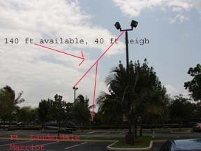
wires I might add would interfere with the 40 meter wire beam. On the road again to the next available site, which happened to be a parking lot near the hotel for a college, Gulf Coast Community College, low and behold it’s usually empty at night and it had 2 appropriately spaced light posts about 40 ft high and 130 ft apart.

If you are afraid of the dark don’t try this, it’s not like sitting at home with the air conditioning on and the amp cranking along. All Battery All the time.

I put together a dipole in the hotel room and drove over to my second new backyard, unlike the 40 meter location, this one has got to be temporary and easy to put up and take down in the dark. With a 2 ounce lead sinker attached to masonry string it was no problem to get over both light posts on the first try, pulled up the 75 meter wire and had a blast on 75 for the first time in months. So what happens now is whenever and wherever I might be driving, I am on the lookout for potential temporary antenna sites. Probably not a bad idea if you are into emergency communications and want to practice your means and methods for getting a signal out during the real thing. Since submitting this article 3 or 4 weeks ago I have added another element, a director, to the 40 meter wire configuration and I am having very consistent results all over the states. Yes it has blown down a couple of times in the very gusty winds of the Gulf of Mexico but for a total investment of less than $75 for a 40 meter beam and a few minutes re stringing it up occasionally I’m not complaining.
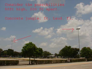
I am now situated in the concrete jungle of West Ft. Lauderdale and ensconced in another hotel, so I am taking my own advice and looking around for possible new temporary wire antenna sites.
Right in the unused part of parking lot of my hotel, could be good north south dipole on 40 meters.


Whoa! This one across the street at Broward Mall looks good, think I’ll ask the Mall manager for permission to try it out at night when mall is closed, will keep you posted if I make bail.

If you are stuck in a restricted apartment, hotel or other RF limited environment, take heart and take a drive, you never know what might be available for a temporary wire antenna experiment, just remember; It’s always easier to get forgiveness than permission.

Tnx for reading,
Bob N4JTE


VERTICALS; GOT 2?
Or how I learned to build a 2 element reversible 3db gain array on the cheap! Submitted by Bob Raynor; N4JTE


I have stayed away from verticals for all the usual reasons, mine being I could never get one to work better than a basic dipole despite all the take off angle advantages etc. When my 40 meter EDZ blew down in a heap last week I was desperate to get my 100 watts back on the air in a hurry with some gain and direction capabilities.

Enter my well worn copy of ON4UN’s Low Band DXing and chapter 11 on vertical arrays. This time I really read and absorbed the concept of radials and phase lines.
I have been spoiled by the luxury of being able to string up 170 ft. at 65 ft for the EDZ and also construct a 2 element 40 meter reversible quad so I figured why not stay in my own backyard for a change and see what this vertical array thing is all about.
If you are interested in getting a real 3db of gain and the ability to reverse direction instantly in a very small footprint please follow along while this die hard vertical hater learns and shares some new tricks. Also please note that I tried this type of array a few years ago with about 80 radials in the ground and it was an abysmal failure so nothing ventured nothing gained.

The Antenna;
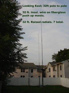
(2) 32ft. long insulated wires supported by fiberglass push up masts at aprox. 40 ft. high. Actually only one mast is the push up type the other was scabbed together using various pieces of fiberglass spreaders. By luck I have two existing 4 by 4 posts aligned sort of East/ West and about ¼ WL apart or in my case, 32 ft. Seems like somebody wanted me to try a 2 element reversible vertical array.

The secret to my success in this venture was to use raised radials, four on the West pole and three on the East pole. The feedpoint ended up at about 8 ft high so running the radials off to 6 ft. high tie off points, (fence, trees etc.) was no big deal and easily removed if needed. The radials on the West pole are relatively symmetrical but the back pole radials are a little contorted due to lack of available space on my property line.


Construct one element at a time and set for resonance at the frequency of choice by checking for lowest swr, with all radials in place, close enough for our purposes. The ultimate goal is to achieve exact self resonance for both verticals at the same frequency. Start off with the antenna and radials the same length, in my case for 7.185 so they were 32 ft of #14 insulated wire. If you need to adjust for resonance do it by changing the wire vertical part, leave the radials alone for the moment. Note; if you need to make drastic ie; more than an inch or two of length changes then something besides mutual loading is screwing with the settings and you might be getting thrown off by a metal fence or other structures nearby, can’t help with that one.

Phase Lines; My other reason for success!

Finally figured out how to use this thing.

I’ve constructed and abandoned driven arrays, both horizontal and vertical, in the past because I’ve always felt a dual trace scope was the only way to make the phase correct but there is another way. Stick with me and wade thru the following steps; worth the trouble.

As per ON4UN’s well researched specifications you will need 2 feedlines of 84 degrees and one delay line of 71 degrees to achieve the benefits of the Christman method and the force feeding of the two elements which is what gives you the gain and direction switching capabilities. All the 50 ohm coax will be cut to the correct degree length using the MFJ with a Tee connector in parallel with a 50 ohm dummy load.

First determine your target frequency; I will use 7.185 for this discussion. As we need (2) feedlines of 84 degree length it’s time for a little theory; A true ¼ WL (90degrees)
piece of 50 ohm coax will show almost 0 swr at it’s electrical length for the frequency of choice when shorted out at the end, FWI, it will do the same at the true ½ wl with the end left open. So we hook up a ¼WL length of coax based on the velocity factor and we are good to go. NOT. Trust me it NEVER works that way. Get the length that way and add a couple of feet. Attach to MFJ and short out the far end and measure for lowest swr and read the freq, in my case a 30 ft. long piece read somewhere around 6.1 megs, way to long. Keep cutting and shorting the far end till you get to the target frequency. An ice pick through the coax is a quicker way. BUT; No matter which method this will give us 90 degrees and we need 84 degrees so it’s time for a little math so we can get the correct target frequency read out on the MFJ to make the phase line SWR zero at 84 degrees, before you cut off too much wire!

Formula; 84/90 x 7.185/x = 7.698 meg
That will be the frequency on the MFJ for 84 degrees.


This method will get you the 71 degree delay line length also. Leave or make all ends bare as you will be hooking the two feedlines to each vertical and the relay and also the 71 degree delay loop to the relay.

RELAY TIME:

PLEASE READ CHAPTER 11-9 Fig. 11-7; ON4UN Low Band DXing for schematic.

Essentially you hook the delay line loop to each of the feedlines at the relay contacts taking care to maintain polarity. In my configuration with the relay off, the loop is leading in the West direction due to the induced phase shift. When 12 volts is applied the loop is now lagging and the direction and gain favors the East. I took a chance and soldered some short hookup wire to the relay contacts for ease of assembly to all the coax feedlines, don’t imagine it makes that much of a difference on the phase lengths considering I had to cut off the connectors on the feedlines after using the MFJ for length calculations. My wiring/ soldering hookup was way too nasty to photograph! This design is for 100 Watts so any higher power will of course need a larger relay.

PERFORMANCE:

It always annoys me when I read all these glowing reports from an enthusiastic antenna owner that to me are worthless unless they are well tested at various times and conditions with a couple of other antennas orientated in a similar direction. For my testing I rehung the 40 meter EDZ ladderline fed at about 50 ft. high in an East/ West take off orientation. I also used a North/ South dipole for further comparison. All were connected to a Delta 4 position antenna switch.
The verticals were extremely competitive with the EDZ and as the sun moved West the verticals were 3 S units louder to Ca. and the Netherlands both on receive and transmit.
The verticals had at least 4 to 5 S unit rejection in the back direction, not fair to the Zepp with gain but showed at least that much with the unity gain dipole.
I did not notice as much noise as expected with verticals unless I went East during the FB barrage here on the East coast at 9pm, I believe that a driven array is slightly less prone to nearby manmade noise.
Some of this may be obvious to the experts out there considering the lower take off angle of the verticals but it was a real revelation to me.

FINAL THOUGHTS;

I believe that any success I achieved with these verticals and none before, was due to using raised radials and cutting phase lines accurately. The added bonus of keeping it all in my own backyard and the simplicity of upkeep and pack up has made this a valuable experiment for me.
I hope this article will encourage others to explore driven arrays and research the amazing amount of reference material out there.
Resources; Relay; Radio shack #IEC255
40ft fiberglass http://www.shop.dx-is.com/
ON4UN’s LowBand DXing.
Tnx for reading
Bob, N4JTE

Tuesday, October 10, 2006

3 element 40 meter reversable quad

3 element 40 meter reversable quad


A; Materials;
1; 3 pushup towers or equivalent capable of 40 feet min height.
2; (3) 8ft 4by4 pressure treated posts minimum 8ft. long.
3; 500 ft #12 insulated wire, home depot.
4; 3 Rolls of masonry string.
5; (3 )Eye hooks or equivalent
6; (2) DTDP relays, clear plastic case, Radio Shack
7; 1 to 1 Balun.
8; 12 volt small supply.
9; 2 wire for power supply to relays.
10; 3 bags sackrete or equivalent for posts setting.

B; Procedure; Physical Antenna.
1; Determine directions of interest, East/West etc, be advised that N/S signals will be greatly diminished.
2; Install 3 wood posts in straight line in direction of interest, maintain 20 ft spacing if possible between posts, smaller spacing will yield smaller gain and front to back.
3; Place eyehooks in top of towers secure with tape. Put end of string thru eye hook and pull thru 40 or so feet, this will be your pulley for the wires and a temp. guy line.
4; Clamp and screw pushups to 3 posts, raise to 40 feet.
5; Determine 40 meter freq. of interest, Divide into 1005 to determine wire length for driven element. Cut wire to length, mark off with electrical tape 4 equal segments from center outward. Do not coil wire leave stretched out.
6; At wire center install 1 to 1 Balun, attach light weight 52 ohm feedline.
7; Raise wire ½ way up mast, attach string to outside corners, raise to top.
8; Pull corners out and attach string to supports that bring corners up to 24 feet aprox. In a straight plane end to end, wire nut remaining ends and tie off to ground stake.
9; Attach feedline to radio, check for resonant frequency with cw or rtty carrier, lowest swr will be resonant frequency. If freq is too low, cut antenna length to achieve or if too high, add wire at bottom corner connection.
10; After achieving resonance, lower antenna and measure total length, write down for future reference. Pull antenna back up to full height.
11; Cut two wires 5% shorter then measured driven length and install on the two outside posts using same procedure as driven element. These become directors.
12; OPTIONAL; but recommended; hook up temp feed line at bottom corners and check resonant frequency, should be 5% higher than driven freq. for example; driven= 7.263 director= 7.626
13; Attach 20 ft of masonry string to top and side corners to maintain element spacing.
14; Guy ropes as required.

NOTE; ANTENNA CAN BE DESIGNED FOR ANY BAND BY EXTRAPOLATING DIMENSIONS.

Procedure; ELECTRICAL ANTENNA

1; Stub construction; Cut two wires to 10% of the driven element length, somewhere around 14 feet depending on resonant freq, Strip both ends for relay connection and fold length in half.
2; Determine terminals that are in the normally closed (connected) position on both relays. Visually or with ohm meter.
3; Solder the stub to the NC terminals, this will be your rear element reflector stub with 12volts off. Solder short wire to the normally open terminals.
4; Solder the stub to the NO terminals, this will be your front element director stub with 12 volts off. Solder short wire to the normally closed terminals.
5; Lower both director elements and insert relays, take care to maintain preference direction with 12 volts off configuration. Solder antenna to center terminals and solder 12 volt supply wire to bottom terminals. Mount relay on flat piece of plexiglass or equivalent and waterproof. Raise both elements back to top of masts, maintain good separation of 12volt supply wire from elements.
6; The 12 volt supply line should of course activate both relays simultaneously so a Y configuration is appropriate.

ON AIR CHECKS
1; Use of tuner is highly recommended for max efficiency. Tune for lowest swr in chosen direction and check opposite direction swr, careful tuner adjustment should yield close to one to one in both directions.
2; Depending on prop, check for good stateside signal, turn on relays and watch for 3 to 5 S unit drop. Do the same to the east, use FB carrier as signal if no other station is available, expect 5 to 7 S unit change, this will be your transmitted power difference in either direction also.

GOOD LUCK AND LET ME KNOW HOW IT WORKS.
Bob, N4JTE

2 element 40 meter reversable quad

2 element 40 meter reversable quad


I have always endeavored to achieve that elusive free 3db of transmitted and received gain on 40 meters with a cheap wire antenna configuration. Doubling your power out without impacting your electric bill or your neighbors T.V. is obviously a nice benefit.
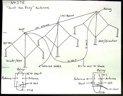
What I would like to describe to you is a 2 element 40 meter diamond shaped quad that is instantly reversible with usable gain and effective front to back rejection which I have affectionately named the “Just Too Easy” antenna.

There is nothing magical here that has not been done before but I was consistently disappointed with the many experiments I’ve tried using every conceivable configuration of phased lines, delay lines, and forced feeding methods ad nauseam to achieve more gain and direction switching abilities with no discernable improvement from one to the next. I figured lets stick to the physical known properties of 2 element parasitic wires. Perhaps my experiences and application might be of use to other wire antenna experimenters.
Admittedly some of my methods border on crude by most standards but my problem is I need instant gratification, {usually in the middle of a G2 storm} and if the sucker works then I will button everything up till the next big idea comes along.

First the basic configuration; Two push up masts at 40 feet tall are spaced at 20 feet apart and attached to 8ft. 4x4 pressure treated posts sunk in the ground a couple of feet. Before raising the masts I attached an eye hook thru which the end of masonry string is run for pulling up the wires and the 52 ohm feedline and one to one balun on the driven element.
Using the standard formula of 1005 divided by frequency, {7.263}, I measured out 138 feet of #12 insulated wire from Home Depot and marked with electrical tape the 4 equal sides. The diamond shape allowed me to feed the driven element at the top, {40ft.}. I used a 40ft. length of RG 58 for it lightness and then attached RG213 for the run back to the shack. The outside corners were tied off to available supports about 24 feet high and the bottom corner {about 2 ft. off the ground} was tied down to a wood stake. The antenna is not perfectly symmetrical as I would have needed a 48 foot high mast with the bottom corner still ending up at ground level.

The second element {director/reflector} was cut to director length, 133ft. and raised to the top of second mast and tied off. The top and outside corners of each element are tied to each other with 20ft. of string to maintain spacing. The Physical antenna is now up in the air but that’s just the beginning. The Electrical antenna must now be tuned and adjusted.

I have the MFJ antenna analyzer but it stayed on the bench for this one as I prefer to check antenna resonance at the radio so the feedline and antenna properties are examined as part of the circuit. With the driven element connected to the radio in the cw mode, 5 watts is applied and a quick sweep for lowest swr is checked for and noted; that will be the resonant frequency. I needed to add about 16in. of wire to the bottom corner to achieve resonance with 139ft 4in. overall length resulting for 7.263. The swr measured 1.4 to one.
That being done it’s on to the director where I attached a temporary feedline to the bottom corner and the procedure was repeated. This time I was looking for resonance around 7.650 to achieve the 5% shortening needed for director length, first try was good, {don’t count on that} and the director was lowered for the next step.
Using the now resonant driven element length of 139ft 4in. as my constant I cut a 14ft. piece of wire,{10%} longer than driven and folded in half to form into stub. This would become the extra length of wire needed to change the director to reflector physically and electrically. A resonance test was done again with the 14ft. stub added into the antenna at the top corner and it was found to be about 9in too long to achieve my target frequency of 6.900 for reflector length. After getting it correct I disconnected the temporary feed line and wire nutted and taped the antenna ends back together. Time to get the reverse capability into the mix.
Radio Shack sells a DTDP 12 volt relay for about $6. and it was just what I needed to accomplish my goal. The direction of choice from here in upstate NY is West so I wanted the reflector stub in the circuit with the relay off. After lowering the director element, {last time, I promise} and opened up the top corner, it was time to insert the relay. The 13ft 3in. stub ends were soldered to the normally closed lugs. The antenna ends were soldered to the center lugs and a shorting wire was soldered across the normally open {director}lugs so that the application of 12 volts would short out the reflector stub and the director would now be functioning{East}. I waterproofed the relay and connections and ran some insulated double wire back to the switched 12v supply in the shack for the relay. Pulled it all back up to top while maintaining a good separation between antenna element and the 12 volt supply wire and tied off. Time for the moment of truth; or consequences.

On air results have been exceptional and made all that walking back and forth to the radio more than worth it. At .15W/L this is a really low antenna but I am truly impressed with the results. I am fortunate that I have 40 to 50 well familiar stations around the country and a few benchmark Eastern DX stations that I have communicated with nightly on the Omiss net for years. Taking into account propagation conditions etc, this real world antenna testing is an invaluable resource. Thanks guys for putting up with me.
The real fun comes with a flick of the switch from west to east with a G0 in Ireland and a CU2 in the Azores reporting a 4 to 5 S unit increase in signal strength while West reports a 5 S unit decrease, that’s a lot of DB’s. Of course at night, the downside to this, is that the foreign broadcast is pounding in; but clicking back to the West direction takes care of that in a heartbeat.

So; appreciable gain in the selected direction with resulting front to back rejection of equal or better value from 2 elements at less than ¼ w/l high from this easily constructed wire antenna makes this one definitely “ A Keeper”. Can’t wait for winter conditions.
N4JTE, Bob
Need more info ? email bobr1919@hotmail.com