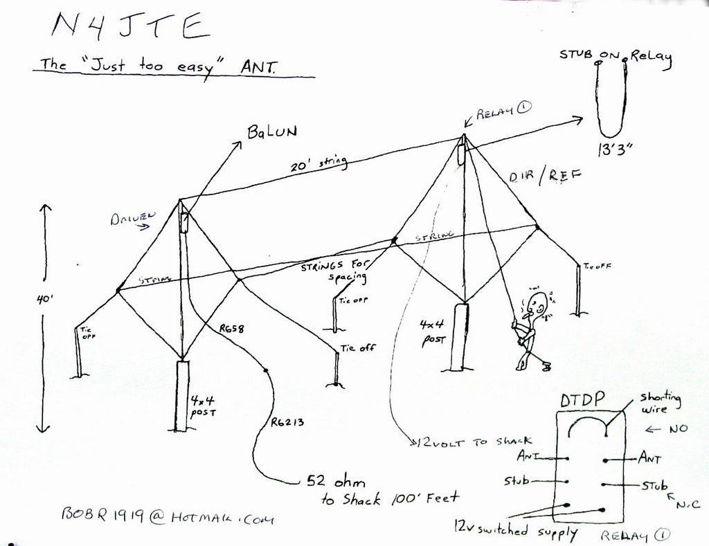
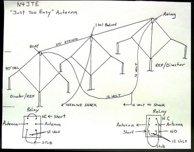
3 element 40 meter reversable quad
3 element 40 meter reversable quad
A; Materials;
1; 3 pushup towers or equivalent capable of 40 feet min height.
2; (3) 8ft 4by4 pressure treated posts minimum 8ft. long.
3; 500 ft #12 insulated wire, home depot.
4; 3 Rolls of masonry string.
5; (3 )Eye hooks or equivalent
6; (2) DTDP relays, clear plastic case, Radio Shack
7; 1 to 1 Balun.
8; 12 volt small supply.
9; 2 wire for power supply to relays.
10; 3 bags sackrete or equivalent for posts setting.
B; Procedure; Physical Antenna.
1; Determine directions of interest, East/West etc, be advised that N/S signals will be greatly diminished.
2; Install 3 wood posts in straight line in direction of interest, maintain 20 ft spacing if possible between posts, smaller spacing will yield smaller gain and front to back.
3; Place eyehooks in top of towers secure with tape. Put end of string thru eye hook and pull thru 40 or so feet, this will be your pulley for the wires and a temp. guy line.
4; Clamp and screw pushups to 3 posts, raise to 40 feet.
5; Determine 40 meter freq. of interest, Divide into 1005 to determine wire length for driven element. Cut wire to length, mark off with electrical tape 4 equal segments from center outward. Do not coil wire leave stretched out.
6; At wire center install 1 to 1 Balun, attach light weight 52 ohm feedline.
7; Raise wire ½ way up mast, attach string to outside corners, raise to top.
8; Pull corners out and attach string to supports that bring corners up to 24 feet aprox. In a straight plane end to end, wire nut remaining ends and tie off to ground stake.
9; Attach feedline to radio, check for resonant frequency with cw or rtty carrier, lowest swr will be resonant frequency. If freq is too low, cut antenna length to achieve or if too high, add wire at bottom corner connection.
10; After achieving resonance, lower antenna and measure total length, write down for future reference. Pull antenna back up to full height.
11; Cut two wires 5% shorter then measured driven length and install on the two outside posts using same procedure as driven element. These become directors.
12; OPTIONAL; but recommended; hook up temp feed line at bottom corners and check resonant frequency, should be 5% higher than driven freq. for example; driven= 7.263 director= 7.626
13; Attach 20 ft of masonry string to top and side corners to maintain element spacing.
14; Guy ropes as required.
NOTE; ANTENNA CAN BE DESIGNED FOR ANY BAND BY EXTRAPOLATING DIMENSIONS.
Procedure; ELECTRICAL ANTENNA
1; Stub construction; Cut two wires to 10% of the driven element length, somewhere around 14 feet depending on resonant freq, Strip both ends for relay connection and fold length in half.
2; Determine terminals that are in the normally closed (connected) position on both relays. Visually or with ohm meter.
3; Solder the stub to the NC terminals, this will be your rear element reflector stub with 12volts off. Solder short wire to the normally open terminals.
4; Solder the stub to the NO terminals, this will be your front element director stub with 12 volts off. Solder short wire to the normally closed terminals.
5; Lower both director elements and insert relays, take care to maintain preference direction with 12 volts off configuration. Solder antenna to center terminals and solder 12 volt supply wire to bottom terminals. Mount relay on flat piece of plexiglass or equivalent and waterproof. Raise both elements back to top of masts, maintain good separation of 12volt supply wire from elements.
6; The 12 volt supply line should of course activate both relays simultaneously so a Y configuration is appropriate.
ON AIR CHECKS
1; Use of tuner is highly recommended for max efficiency. Tune for lowest swr in chosen direction and check opposite direction swr, careful tuner adjustment should yield close to one to one in both directions.
2; Depending on prop, check for good stateside signal, turn on relays and watch for 3 to 5 S unit drop. Do the same to the east, use FB carrier as signal if no other station is available, expect 5 to 7 S unit change, this will be your transmitted power difference in either direction also.
GOOD LUCK AND LET ME KNOW HOW IT WORKS.
Bob, N4JTE
posted by skywalker at 1:39 PM
3 comments
![]()