Thursday, July 10, 2008

Wire Antennas: The Good, Bad, and The Ugly:

Tuesday, July 08, 2008


N4JTE; On the Road Again
Where there is a will; there is a way!

Thoughts on getting an antenna up and working in challenging situations.


I am in the construction industry and with the economy in major upheaval I had to leave behind a very nice antenna farm in my backyard in upstate NY and get on the road to pay the bills.

Yep, there is an antenna or two in there, trust me!

First stop was Ft. Lauderdale, Florida for a couple of months R&R and a lame attempt at a job search while enjoying the view and the ocean. I missed ham radio and decided to attempt to lasso a nice 70 foot palm tree next to my triplex on the beach and enjoy the best of all worlds, ham radio and the ocean, alas it was not to be as my attempt to get a line over the tree ended up circumnavigating 2 hotels further down the street and sending about 200 yards of fishing line over their roofs, landlady was not too pleased, never liked her anyway.

Next stop, Panama City Beach, Fl. and due to the largesse of my new client I was stuck in a Sleep Inn on the second floor with no way of sticking any antenna out the window so it was time to get a little more adventurous, which is, finally, the point of this article . My goal was to get a decent 40 meter wire up to run from my parked truck and reacquaint myself with many friends from the OMISS net, I say wire because I have never been a real mobile operator and appreciate the operators who do it well on a consistent basis. First attempt was a wire vertical on a fiberglass pushup mast right on the Gulf with 4 radials, tie wrapped to a stop sign at the boat launch ramp, expected big reports and solid qso’s, actually on first CQ I was told my signal though strong, was totally distorted. Major disappointment but I have never been too good with verticals and then I figured out my battery connection and wire was pretty amateurish with obvious problems. So I took a drive around and spotted what looked like a demolished building site about one mile from my hotel with a For Sale sign, abandoned parking lot and a few trees that looked promising.
Add a little wire, couple of trees or light posts, instant antenna.

A quick trip to home depot for a 500 ft roll of #12 insulated wire and good old radio shack for some RG 58 feedline and off to my new backyard for some antenna hoisting. Keeping a wary eye out for the antenna police I strung up a basic 40 meter dipole between two trees about 50ft high with my trusty fishing rod and masonry string and made a couple of contacts, audio was fine and signal strength was reported as 5/9 in Colorado at 3pm CST, now we’re cooking!

On a happy roll I figured why not try a reflector behind the dipole and threw one up using the same trees with around 20 ft. of spacing and voila when it got dark it worked so well I was told my signal at 100 watts fixed mobile rivaled my home installation in NY with a 2 element 40 meter quad and the AL 1500. Yeah I know, it’s all about propagation and the salt water but it was sure nice to be heard again with a decent signal.

Very rewarding to be able to run a WAS net again on 40 meters during a major contest but of course as any antenna nut knows there is always the challenge to make it better so in my case I wanted to get back on 75 meters with a decent signal, so after surveying the present available trees I figured any

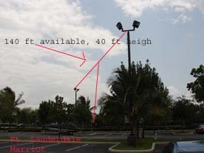
wires I might add would interfere with the 40 meter wire beam. On the road again to the next available site, which happened to be a parking lot near the hotel for a college, Gulf Coast Community College, low and behold it’s usually empty at night and it had 2 appropriately spaced light posts about 40 ft high and 130 ft apart.

If you are afraid of the dark don’t try this, it’s not like sitting at home with the air conditioning on and the amp cranking along. All Battery All the time.

I put together a dipole in the hotel room and drove over to my second new backyard, unlike the 40 meter location, this one has got to be temporary and easy to put up and take down in the dark. With a 2 ounce lead sinker attached to masonry string it was no problem to get over both light posts on the first try, pulled up the 75 meter wire and had a blast on 75 for the first time in months. So what happens now is whenever and wherever I might be driving, I am on the lookout for potential temporary antenna sites. Probably not a bad idea if you are into emergency communications and want to practice your means and methods for getting a signal out during the real thing. Since submitting this article 3 or 4 weeks ago I have added another element, a director, to the 40 meter wire configuration and I am having very consistent results all over the states. Yes it has blown down a couple of times in the very gusty winds of the Gulf of Mexico but for a total investment of less than $75 for a 40 meter beam and a few minutes re stringing it up occasionally I’m not complaining.
I am now situated in the concrete jungle of West Ft. Lauderdale and ensconced in another hotel, so I am taking my own advice and looking around for possible new temporary wire antenna sites.
Right in the unused part of parking lot of my hotel, could be good north south dipole on 40 meters.


Whoa! This one across the street at Broward Mall looks good, think I’ll ask the Mall manager for permission to try it out at night when mall is closed, will keep you posted if I make bail.

If you are stuck in a restricted apartment, hotel or other RF limited environment, take heart and take a drive, you never know what might be available for a temporary wire antenna experiment, just remember; It’s always easier to get forgiveness than permission.

Tnx for reading,
Bob N4JTE


VERTICALS; GOT 2?
Or how I learned to build a 2 element reversible 3db gain array on the cheap! Submitted by Bob Raynor; N4JTE


I have stayed away from verticals for all the usual reasons, mine being I could never get one to work better than a basic dipole despite all the take off angle advantages etc. When my 40 meter EDZ blew down in a heap last week I was desperate to get my 100 watts back on the air in a hurry with some gain and direction capabilities.

Enter my well worn copy of ON4UN’s Low Band DXing and chapter 11 on vertical arrays. This time I really read and absorbed the concept of radials and phase lines.
I have been spoiled by the luxury of being able to string up 170 ft. at 65 ft for the EDZ and also construct a 2 element 40 meter reversible quad so I figured why not stay in my own backyard for a change and see what this vertical array thing is all about.
If you are interested in getting a real 3db of gain and the ability to reverse direction instantly in a very small footprint please follow along while this die hard vertical hater learns and shares some new tricks. Also please note that I tried this type of array a few years ago with about 80 radials in the ground and it was an abysmal failure so nothing ventured nothing gained.

The Antenna;
(2) 32ft. long insulated wires supported by fiberglass push up masts at aprox. 40 ft. high. Actually only one mast is the push up type the other was scabbed together using various pieces of fiberglass spreaders. By luck I have two existing 4 by 4 posts aligned sort of East/ West and about ¼ WL apart or in my case, 32 ft. Seems like somebody wanted me to try a 2 element reversible vertical array.

The secret to my success in this venture was to use raised radials, four on the West pole and three on the East pole. The feedpoint ended up at about 8 ft high so running the radials off to 6 ft. high tie off points, (fence, trees etc.) was no big deal and easily removed if needed. The radials on the West pole are relatively symmetrical but the back pole radials are a little contorted due to lack of available space on my property line.


Construct one element at a time and set for resonance at the frequency of choice by checking for lowest swr, with all radials in place, close enough for our purposes. The ultimate goal is to achieve exact self resonance for both verticals at the same frequency. Start off with the antenna and radials the same length, in my case for 7.185 so they were 32 ft of #14 insulated wire. If you need to adjust for resonance do it by changing the wire vertical part, leave the radials alone for the moment. Note; if you need to make drastic ie; more than an inch or two of length changes then something besides mutual loading is screwing with the settings and you might be getting thrown off by a metal fence or other structures nearby, can’t help with that one.

Phase Lines; My other reason for success!

Finally figured out how to use this thing.

I’ve constructed and abandoned driven arrays, both horizontal and vertical, in the past because I’ve always felt a dual trace scope was the only way to make the phase correct but there is another way. Stick with me and wade thru the following steps; worth the trouble.

As per ON4UN’s well researched specifications you will need 2 feedlines of 84 degrees and one delay line of 71 degrees to achieve the benefits of the Christman method and the force feeding of the two elements which is what gives you the gain and direction switching capabilities. All the 50 ohm coax will be cut to the correct degree length using the MFJ with a Tee connector in parallel with a 50 ohm dummy load.

First determine your target frequency; I will use 7.185 for this discussion. As we need (2) feedlines of 84 degree length it’s time for a little theory; A true ¼ WL (90degrees)
piece of 50 ohm coax will show almost 0 swr at it’s electrical length for the frequency of choice when shorted out at the end, FWI, it will do the same at the true ½ wl with the end left open. So we hook up a ¼WL length of coax based on the velocity factor and we are good to go. NOT. Trust me it NEVER works that way. Get the length that way and add a couple of feet. Attach to MFJ and short out the far end and measure for lowest swr and read the freq, in my case a 30 ft. long piece read somewhere around 6.1 megs, way to long. Keep cutting and shorting the far end till you get to the target frequency. An ice pick through the coax is a quicker way. BUT; No matter which method this will give us 90 degrees and we need 84 degrees so it’s time for a little math so we can get the correct target frequency read out on the MFJ to make the phase line SWR zero at 84 degrees, before you cut off too much wire!

Formula; 84/90 x 7.185/x = 7.698 meg
That will be the frequency on the MFJ for 84 degrees.


This method will get you the 71 degree delay line length also. Leave or make all ends bare as you will be hooking the two feedlines to each vertical and the relay and also the 71 degree delay loop to the relay.

RELAY TIME:

PLEASE READ CHAPTER 11-9 Fig. 11-7; ON4UN Low Band DXing for schematic.

Essentially you hook the delay line loop to each of the feedlines at the relay contacts taking care to maintain polarity. In my configuration with the relay off, the loop is leading in the West direction due to the induced phase shift. When 12 volts is applied the loop is now lagging and the direction and gain favors the East. I took a chance and soldered some short hookup wire to the relay contacts for ease of assembly to all the coax feedlines, don’t imagine it makes that much of a difference on the phase lengths considering I had to cut off the connectors on the feedlines after using the MFJ for length calculations. My wiring/ soldering hookup was way too nasty to photograph! This design is for 100 Watts so any higher power will of course need a larger relay.

PERFORMANCE:

It always annoys me when I read all these glowing reports from an enthusiastic antenna owner that to me are worthless unless they are well tested at various times and conditions with a couple of other antennas orientated in a similar direction. For my testing I rehung the 40 meter EDZ ladderline fed at about 50 ft. high in an East/ West take off orientation. I also used a North/ South dipole for further comparison. All were connected to a Delta 4 position antenna switch.
The verticals were extremely competitive with the EDZ and as the sun moved West the verticals were 3 S units louder to Ca. and the Netherlands both on receive and transmit.
The verticals had at least 4 to 5 S unit rejection in the back direction, not fair to the Zepp with gain but showed at least that much with the unity gain dipole.
I did not notice as much noise as expected with verticals unless I went East during the FB barrage here on the East coast at 9pm, I believe that a driven array is slightly less prone to nearby manmade noise.
Some of this may be obvious to the experts out there considering the lower take off angle of the verticals but it was a real revelation to me.

FINAL THOUGHTS;

I believe that any success I achieved with these verticals and none before, was due to using raised radials and cutting phase lines accurately. The added bonus of keeping it all in my own backyard and the simplicity of upkeep and pack up has made this a valuable experiment for me.
I hope this article will encourage others to explore driven arrays and research the amazing amount of reference material out there.
Resources; Relay; Radio shack #IEC255
40ft fiberglass http://www.shop.dx-is.com/
ON4UN’s LowBand DXing.
Tnx for reading
Bob, N4JTE